The M2 is a striking high performance SBC compared to the M1 series We launched the ODROID-M1 about 2 years ago, and the ODROID-M1S about 1 year ago. Both models have been successfully supplied and continue to be adopted as core components in embedded systems by our B2B customers. We received feedback that the performance and input/output port configuration of the ODROID-M1/M1S were sufficient for most embedded systems. However some customers still wanted higher-end models equipped with high-performance processors. To meet the demand for higher performance computing power required by important industrial embedded system builders, we are launching the new ODROID-M2 SBC today. Compared to the original ODROID-M1 (based on the RK3568B2 SoC), the ODROID-M2 uses the RK3588S2 SoC whose comparative characteristics are listed below: Multiprocessing performance is about 3 times faster. LPDDR5 64-bit RAM with a memory bandwidth that is more than twice higher. A GPU that is more than 5 times faster. A NPU that is more than 3 times faster. An on-board 64GB eMMC storage device which is twice faster thanks to a HS400 interface. More information : https://www.hardkernel.com/shop/odroid-m2-with-16gbyte-ram/
The H4 Cube Case can embed an ODROID-H4, H4+ or H4 Ultra board with optional two 2.5″ SATA SSDs, as well as a Net Card and a 92x92x15mm cooling fan. There are four USB ports on the front panel allowing you to easily connect game controllers or input/output devices.
2.5” SATA SSDs (or HDDs) can only be used with the ODROID-H4+ or H4 Ultra. The ODROID-H4 does not include SATA ports. Alternatively, you can use an M.2 2×2 Card (in place of the Net Card) + 2 NVMe SSDs with any of the three H4 board models.
Passionate “old-school” game players from the early 2000’s will be smiling with nostalgia at our homage to a legendary game console released in 2001.
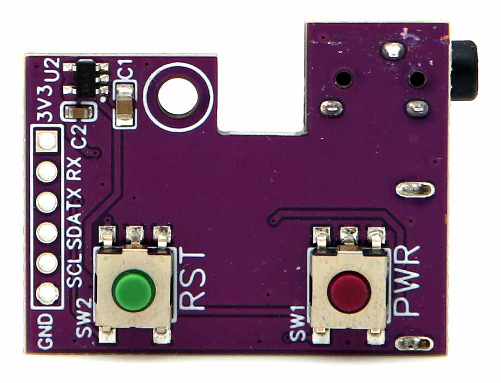
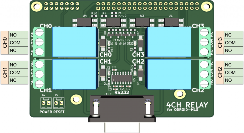
There is a power button with a red LED and a function button with a green LED which is configurable.
The green LED can be controlled by the RTS signal, and the user configurable Function button status can be read by the CTS signal through the 24-pin IO header, so they can be accessed with a simple Python script on Linux. Please refer to this link for the details: How to access the user button and LED
Its shape is close to a cube with size of 150x157x110mm. A big handle on the rear side helps you carry the H4 Cube Case around.
Components in the box
Case Top
Case Bottom
Front panel
USB hub board
Rear panel
SATA SSD bracket x 2
Cushion for SATA SSD x 2
M3 screw x 4
Screw for plastic parts x 13
Rubber feet x 4
Screwdriver x 1
20mm PCB support plastic M3 x 2 (to be used when a Net Card or M.2 2×2 Card is not installed)
16mm PCB support metal M3 x 2 (to be used when a Net Card or M.2 2×2 Card is installed)
After the commercial success of the NetCard 2.5 GbE for the ODROID-H series, we looked into how we could provide new add-on cards to extend further the versatility of your ODROID-H4.
Note: This product is not compatible with the ODROID-H2, H3 series.
The M.2 screws are pre-installed. (4 pcs)
The M.2 4×1 card, provides four M.2 PCIe Gen 3 x1 lanes connectors instead. It allows you to use four M.2 devices: any combination of NVMe drives, Network adapters, WiFi adapters, 5G adapters, etc that leverage the bandwidth of PCIe Gen 3 x1 lane.
Because the PCIe Gen 3 configuration (bifurcation) is embedded in Intel microcode that is merged into the BIOS bin file at build time, you need to flash a different version of the BIOS to use one of these two new cards. The M.2 4×1 card requires the same BIOS version as the NetCard 2.5 GbE. You find this BIOS on the Wiki pages for the H3 and H4.
Important Note: Make sure to select the right BIOS, for the H4 or for the H3.
Like the NetCard 2.5 GbE, these two new cards are installed under the mainboard, they slide into the mainboard M.2 connector and then are screwed to fix them solidly.
Thanks to this integration, these two new cards are compatible with all the ODROID-H3 and ODROID-H4 series. Note however that if you use tall M.2 devices, you may have to select a case that provides enough bottom vertical space.
M.2 4×1 card (Compatible with ODROID-H4 series only)
You can install four 2280-sized M.2 PCIe devices, and each slot has one PCIe 3.0 lane (1 x 8GT/s)
Multiple SSDs can be installed using the JBOD (Just Bunch of Disks) concept. Since it only uses one PCIe lane per slot, the original PCIe speed is reduced to a quarter, but you can still access files up to 800~900MB/s.
Or you can install PCIe devices such as WiFi, 5GbE Ethernet, 4G/5G modem, AI accelerator TPU/NPU, etc. in M.2 form factor.
As stated earlier, you have to flash another ESF BIOS for 4 bifurcated x1 lanes, since the default BIOS provides non-bifurcated x4 lanes.
Typical Use Cases
These two new M.2 cards are intended for any ODROID-H4 or ODROIR-H3 who want to split off the PCIe Gen 3 x4 lanes for use with two x2 lanes or four x1 lane devices, at the expense of the max theoretical speed provided to each device.
Use Cases
You want as much SSD space as possible:
The M.2 2×2 card with 2 x 4TB NVMe SSD provides 8TB of SSD space.
The M.2 4×1 card with 4 x 4TB NVMe SSD provides 16TB of SSD space.
While keeping an SSD at PCIe Gen 3 x2 or x1 speed, you want to use one of several extra network adapters, a PCI WiFi adapter, a 5G adapter, a PCIe AI adapter, etc.
If your goal is to use an M.2 NVMe SSD at maximum speed (4 x 8GT/sec), keep using the PCIe Gen 3 x4 lanes fully dedicated to the NVMe SSD.
Informational Benchmark
Using a generic NVMe SSD we measured and compared the throughput you gain in each configuration, we also measured the throughput of a 128GB eMMC and a SATA SSD, all using ioZone 3.
We obtained the following results:
The obvious first remark is that reducing the PCIe throughput by a factor of 2 or 4 does not mean the speed of your SSD will also be divided by the factors. The reason is that your NVMe SSD also has its own limits no matter how fast is the PCIe channel(s). The second remark is that in both cases, M.2 2×2 or M.2 4×1 card, the NVMe SSD still provides faster speeds than the SATA SSD and eMMC.
Product Compatibility
H2 Series
H3 Series
H4 Series
NetCard v1 (2.5GbE)
Yes
Yes
Yes
NetCard v2 (2.5GbE)
Yes
Yes
Yes
M.2 2×2 Card
No (1)
Yes
Yes
M.2 4×1 card
No / Maybe (2)
No / Maybe (2)
Yes
(1) The H2 CPU (Celeron J4115) does not support the 2×2 PCIe bifurcation. (2) The M.2 4×1 card has a larger footprint and does not physically fit under the H2 or H3 boards. Therefore, the card cannot be fixed directly to the board like with a H4. HOWEVER, if you can find an M.2 male/female extension cable plus perform some additional DIY for mounting the card in your box or case, you can use the M.2 4×1 card with the H2 or H3.
Again, the new generation is more powerful and offers higher performance. It also delivers key new IO that will please many users.
Introducing the ODROID-H4, H4+ and H4 Ultra
Hardkernel is introducing the ODROID-H4, H4+ and H4 Ultra, which is equipped with higher performance and richer interfaces.
The major characteristics of the ODROID-H4 series compared to the ODROID-H3 series are:
Faster CPU architecture Alder Lake N vs. Jasper Lake. Plus AVX2 extensions.
Faster DRAM interface DDR5 4800 MT/s vs. DDR4 2933 MT/s.
Higher base and boost CPU frequencies and more powerful iGPU.
The increase from 2 to 4 SATA ports allows connection to a greater number of storage devices, ODROID-H4+ and ODROID H4 Ultra only.
An additional DisplayPort added allows the simultaneous use of up to 3 monitors.
Low cost ODROID H4 for compute and graphics applications (e.g signage, robot, factory automation,..)
Flagship H4 Ultra doubling the number of CPU cores, from 4 to 8 cores.
We also implemented little details following the ODROID-H3 feedback we receive from all of our users, this means you. Examples:
Dual BIOS: If the BIOS is corrupted due to a power outage during update, etc., you can boot into the backup BIOS and recover by moving the jumper next to the DC jack. This feature is only available on ODROID-H4+ and ODROID H4-Ultra.
The new H4 cases format has been improved so that a cooling fan can be mounted inside the case.
A Mini-ITX kit for seamless integration with generic ITX PC cases.
Let’s look at the detailed table shown below.
ODROID
H2+
(‘2020 Jun)
ODROID
H3
(‘2022 Oct)
ODROID
H3+
(‘2022 Oct)
ODROID
H4
(‘2024 Apr)
ODROID
H4+
(‘2024 Apr)
ODROID
H4 Ultra
(‘2024 Apr)
Processor
CPU (Intel)
Celeron J4115
Celeron N5105
Pentium N6005
Processor N97
Processor N97
Core™ i3 Processor N305
Code name
Gemini Lake
Jasper Lake
Jasper Lake
Alder Lake-N
Alder Lake-N
Alder Lake-N
Launch date
Q4’17
Q1’21
Q1’21
Q1’23
Q1’23
Q1’23
Microarchitecture
Goldmont Plus
Tremont
Tremont
Gracemont
Gracemont
Gracemont
Cores / Threads
4C4T
4C4T
4C4T
4C4T
4C4T
8C8T
Cache
4 MB
4 MB
4 MB
6 MB
6 MB
6 MB
AVX2 (Advanced Vector Extensions)
No
No
No
Yes
Yes
Yes
TDP
10W
10W
10W
12W
12W
15W
Single Thread Burst Frequency (GHz)
2.5
2.9
3.3
3.6
3.6
3.8
Memory
Max. Memory address space (GB)
32
64
64
48
48
48
Max. Memory Speed (MT/s)
DDR4-2400
DDR4-2933
DDR4-2933
DDR5-4800
DDR5-4800
DDR5-4800
iGPU (Intel UHD Graphics)
Burst Frequency (MHz)
750
800
900
1200
1200
1250
Execution Units
12
24
32
24
24
32
Video outputs
HDMI
1
1
1
1
1
1
DisplayPort
1
1
1
2
2
2
PCIe (via NVMe slot)
Generation
Gen 2
Gen 3
Gen 3
Gen 3
Gen 3
Gen 3
Lanes
4
4
4
4
4
4
Compatibility with optional 4-ports 2.5GbE Net Card
Yes
Yes
Yes
Yes
Yes
Yes
IO ports
USB 2.0
2 ports
2 ports
2 ports
2 ports
2 ports
2 ports
USB 3.0
2 ports
2 ports
2 ports
2 ports
2 ports
2 ports
2.5GbE
2 ports
2 ports
2 ports
1 port
2 ports
2 ports
SATA III
2 ports
2 ports
2 ports
No
4 ports
4 ports
24pin IO Expansion ports
I2C x 2
I2C x 2
I2C x 2
I2C x 2
I2C x 2
I2C x 2
USB 2.0 x 1
USB 2.0 x 3
USB 2.0 x 3
USB 2.0 x 3
USB 2.0 x 3
USB 2.0 x 3
UART x 2
UART x 1
UART x 1
UART x 1
UART x 1
UART x 1
HDMI-CEC x 1
HDMI-CEC x 1
HDMI-CEC x 1
HDMI-CEC x 1
HDMI-CEC x 1
HDMI-CEC x 1
Ext. Power Button x 1
Ext. Power Button x 1
Ext. Power Button x 1
Ext. Power Button x 1
Ext. Power Button x 1
Ext. Power Button x 1
Others
Optional Cooling Fan
92 mm 5 Volt
mini 4pin connector
92-25 mm 12 Volt
standard PC 4-pin
92-25 mm 12 Volt
standard PC 4-pin
Slim 92-15 or thick 92-25 mm 12 Volt
standard PC 4-pin
Slim fan fits inside the new cases.
Slim 92-15 or thick 92-25 mm 12 Volt
standard PC 4-pin
Slim fan fits inside the new cases.
Slim 92-15 or thick 92-25 mm 12 Volt
standard PC 4-pin
Slim fan fits inside the new cases.
Dimensions
110x110mm (4.3×4.3 in)
110x110mm (4.3×4.3 in)
110x110mm (4.3×4.3 in)
120x120mm (4.7×4.7 in)
120x120mm (4.7×4.7 in)
120x120mm (4.7×4.7 in)
Recommended Power Supply 1
60W
60W
60W
60W
60W
60W
Recommended Power Supply 2 for supporting booting with 3.5″ hard disks
133W
133W
133W
133W
133W
133W
Unlimited Performance Mode
No
Yes
Yes
Yes
Yes
Yes
Security (TPM 2.0)
Couldn’t be supported
fTPM enabled
(Will run Windows 11 out of the box)
Hardkernel H-series cases
DIY assembly
Translucent Blue Acrylic
DIY assembly
The cases are made of solid and sturdy PCBs.
DIY assembly
The cases are made of solid and sturdy PCBs.
A classic GameCube-style case will be released in May or June separately.
Certifications
FCC/CE/KC/RoHS
FCC/CE/KC/RoHS
FCC/CE/KC/RoHS
FCC/CE/KC/RoHS
FCC/CE/KC/RoHS
FCC/CE/KC/RoHS
Pricing
$119
$129
$165
$99
$139
$220
Noteworthy Features
Why the N97 instead of the N100?
Bigger numbers aren’t always better. INTEL naming may be deceiving.
We chose the N97 because its Maximum Turbo Frequency is 200MHz higher than the N100, respectively 3.60GHz vs. 3.40GHz. In addition, the GPU Max Dynamic Frequency is a whopping 450MHz higher, respectively 1.2GHz vs. 750MHz.
The TDP value of the N97, which is therefore faster than the N100, is higher, but there is almost no difference in power consumption at idle state. Although the N97 is more expensive, we chose it for its higher performance.
Single-Channel Memory
This is a decision made by Intel. The Alder Lake N processors only offer one single-channel of memory. However, the DDR5 speed of 4800 MT/s as well as the Dual Rank (r2x8) option largely compensate for the double-channel of DDR4 with the H2 and H3 series. The DDR5 4800 MT/s of the H4 series leaves the DDR4 2933 MT/s and DDR4 2400 MT/s of the H3 and H2 series in its rear mirror.
Note: While the Intel ARK pages specify the Alder Lake N max. memory to be 16GB, we validated that 32 and 48 GB DDR5 SO-DIMMs 4800 or 5600 MT/s work as well. The 5600 MT/s will run at 4800 MT/s. The Intel specifications for the H2 and H3 processors were limited as well, but many users were able to (respectfully) pump up the max. memory to 32 and 64 GB.
How many SATA ports and video outputs?
Compared to the previous generation Gemini Lake or Jasper Lake, the design flexibility of the new Alder Lake-N’s high-speed signal interface has been significantly reduced. To enable SATA ports inside the SoC, a choice arose: reducing the number of PCIe lanes for NVMe from 4 to 2 or find another way. In order to avoid compromising the speed of NVMe, it was inevitable to add an external, expensive SATA controller.
Thanks to a controller that supports four SATA ports, the requirement to connect many storage devices has been resolved. As the performance of CPU, GPU, and DRAM increases, it has become possible to drive a large number of displays. Therefore, in addition to the one output each for HDMI and DisplayPort in the existing H series, the new H4 series is equipped with an additional DisplayPort, allowing a total of three 4K monitors to be connected simultaneously.
Because there are more connectors with relatively large footprints, the form factor has changed from 110x110mm to 120x120mm, and the area has increased by about 20%. As a result, form factor compatibility with the existing H2/H3 series has unfortunately disappeared. However, this affects only the case compatibility. Accessories such as the Net Card work on H2, H3 and H4 series.
Which H4 model is the best for you?
To allow you to use a high-performance platform at a relatively low cost, we removed all SATA functions, the second Ethernet port, and the Dual-BIOS feature to create a basic H4 model that focuses on cost-effectiveness. Therefore, it is suitable for application to embedded systems such as digital signage or factory automation or robot control.
On the other hand, the H4+ is equipped with four SATA ports, a second Ethernet port, and Dual-BIOS feature, making it the best choice for users who need mass storage for high-performance NAS and/or use it for routing capabilities.
Finally, although it is more expensive, we have also designed the H4 Ultra model, which can take advantage of powerful performance with twice the number of CPU cores (from 4 to 8) and more GPU execution units. Thanks to its many cores and fast clocks, the H4 Ultra model shows computing performance that can be twice as high as the H4 and H4+ models, based on multithreaded computing benchmarking results.
If you are very sensitive to power consumption, the H4 model would be the most desirable option. This is because the power in idle state is about 1 Watt lower than the H4+ model.
Performance
Thanks to the Intel Alder Lake-N Gracemont architecture, the higher frequencies of the N97, for the H4 and H4+, and N305, for the H4 Ultra, coupled with DDR5 4800 MT/s, the H4 and H4+ in UP mode are on average around 36% more performant than the H3+ in UP mode. The increased performance jumps to around 83% for the H4 Ultra, again compared to the H3+ in UP mode. This is what we witnessed while running 206 mostly non-synthetic benchmarks. We review these benchmarks further down. We will also see that the increased performance climbs to even higher numbers for multi-threaded applications.
Versatility
For the last 4 years, We acquired a lot of experience and feedback from users, meaning you, first with the H2 series, then with the H3 series. We have seen and still see an incredible broad range of applications.
Some users pushed their ODROID to the max with as much memory as possible, disks, discrete graphics cards, additional SATA ports cards or high-bandwidth network cards.
Conversely, other users made their ODROID as frugal as possible, chasing the last tenths of Watt that could be saved. In this matter, see section Power Consumption Characteristics, we worked on many aspects to make significantly low idle power consumption possible, as well as documenting and enabling users to know how to reach idle power that is not at all high compared to ARM series boards. We believe this is essential, especially for European users where the cost of electrical energy has been rising for years, to which you add the goal of reducing net greenhouse gas emissions, as targeted by the EU, while running 24×7 systems.
These two extremes, and everything in the middle, are possible because the H series boards can be widely customized. We believe the success of the ODROID H-series is in part due to its original DIY design goal with boards that do not restrict you to one kind of application, e.g. TV box.
The ODROID H4 series doubles down on versatility by adding the low cost H4, with stripped down hardware, on one side of the H4+, and the 8-core H4 Ultra flagship on the other side of the H4+.
The table shown below details the H4 series user-level customizations:
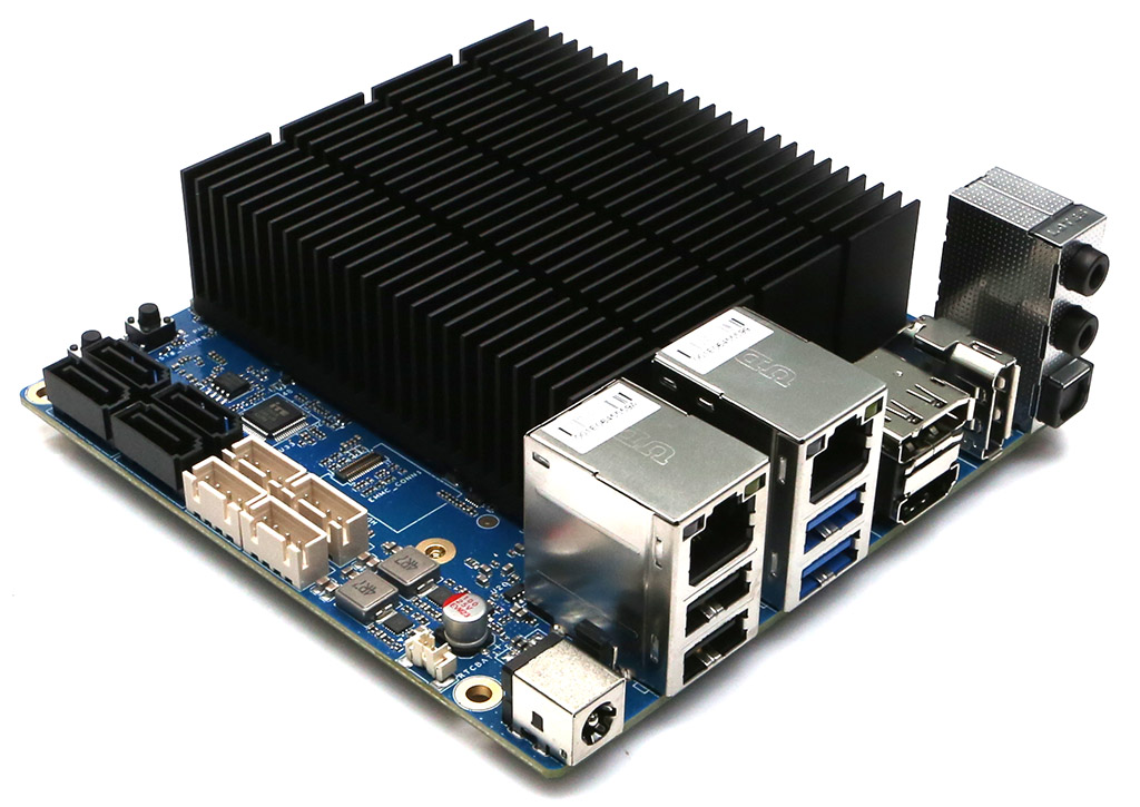
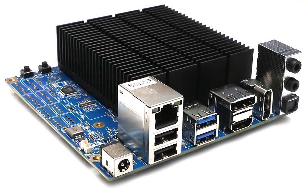
Design
An SBC design that makes sense: all the connectivity is on the rear side, simplifying case design and reducing footprint on a desk.
H-series Net Card
Using the NVMe port, provides 4 additional 2.5 GbE ports, thus tripling the number of 2.5 GbE ports to 6 ports.
Do It Yourself
The ODROID H-series offers you a lot of freedom. You are free to chose:
1. The amount and brand of memory. No soldered memory.
2. The size of the eMMC (including not using one). No soldered eMMC.
3. The size of the NVMe PCIe Gen 3 x4 SSD, including not using one(*).
4. To transform the NVMe slot into a PCIe Gen 3 x4 slot for using PCIe cards via optional adapter cable(*).
5. The size of the 1 to 4 SATA III hard disks or SSDs, including not using them (H4+ and H4 Ultra only).
6. A case among 4 (soon to be 5) types of Hard Kernel cases or use a custom one you design or another user designed or use a mainstream Mini-ITX case thanks to the ODROID H4 Mini-ITX kit.
7. Hard Kernel cases allow the usage of an optional silent fan for optimal thermal performance.
8. Any x86-64 flavor of Windows, Linux or BSD operating systems, etc.
9. To upgrade the hardware later with larger memory, more NVMe or SSD or hard disk space.
10. To maximize performance or to minimize power consumption thanks to well documented BIOS and OS options.
(*) PCIe Gen 2 on the H2/H2+.
Summary
Note: This summary compares the UP versions of the H3+, H4, H4+ and H4 Ultra because we did not run all the benchmarks on the H3+ non-UP. We ran a total number of 206 benchmarks/cases using the UP configurations.
The major facts about these benchmarks are:
The H4 and H4+ UP are on average around 36% more performant than the H3+ UP.
With the H4 Ultra UP, the average climbs to around 83%!
The H4 and H4+ UP can be up to twice faster than the H3+ UP for particular tests.
The H4 Ultra UP can be up to three and a half faster than the H3+ UP for particular tests.
The H4 Ultra UP is on average around 36% more performant than the H4 and H4+ UP.
The H4 Ultra UP can be more than twice faster than the H4 and H4+ UP for particular tests.
Not too surprising, with 8 cores vs. 4 cores, the H4 Ultra UP top performance occurs with multi-threaded applications (e.g. Compilation, Java, Imaging, Stargate, MemCached, OpenSSL, Video Encoding,…) without being kneecapped by thermal throttling, thanks to Unlimited Performance and active cooling.
Demo video
This demo video shows the PS2 and GameCube emulation games on Linux Vulkan GPU driver with Fractional-Scaling technology. We used Batocera.linux x86_64 version 39 for the emulation.
Thanks to the H4’s significantly improved CPU, GPU, and DRAM performance, we can enjoy SD-quality classic masterpiece games in HD quality graphics now. To play games with this level of graphics on the H3 board, we had to connect an external video card.
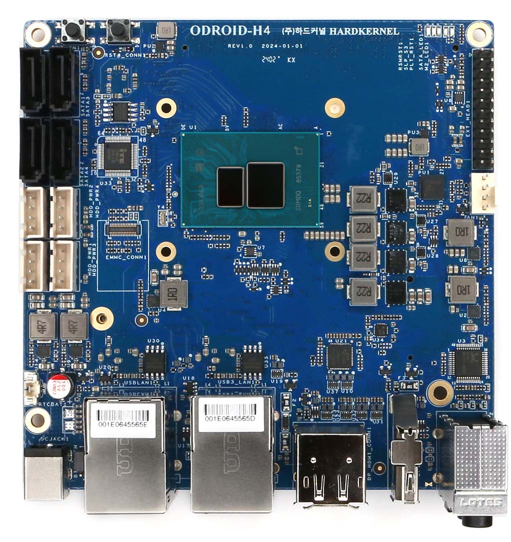
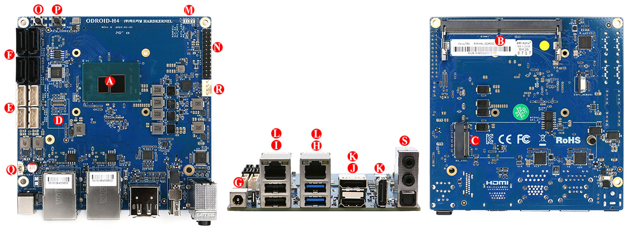
Board Description
A. CPU (Intel N97 or N305 )
B. 1 x DDR5 SO-DIMM slots (Single channel memory support)
C. 1 x M.2 PCI Express Module Socket (NGFF-2280)
D. 1 x eMMC (Embedded Multimedia-Card) Socket
E. 4 x SATA Power Connectors (2.5mm pitch, JST-XH compatible connector)
F. 4 x SATA3 6.0 Gb/s Data Connectors
G. 1 x DC Power Jack
H. 2 x USB 3.0
I. 2 x USB 2.0
J. 1 x HDMI 2.0
K. 2 x DisplayPort 1.2
L. 2 x RJ45 Ethernet Ports (10/100/1000/2500)
M. 5 x System LED Indicators
N. 1 x Peripheral Expansion Header (24-pin)
O. 1 x Power Switch
P. 1 x Reset Switch
Q. 1 x Backup Battery Connector (2-pin)
R. 1 x Active Cooling Fan Connector (4-pin)
S. 1 x Audio out, 1 x Audio in, 1 x SPDIF out
Specifications
Processor
Intel 4-Core N97 for ODROID-H4 and H4+
Intel 8-Core i3 N305 for ODROID-H4 Ultra
Memory
1 x DDR5 SO-DIMM slots
Single Channel, up to 4800 MT/s. Note: Dual rank r2x8 are better.
Max memory capacity 48GB
DDR3/DDR4 are not supported
Storage
1 x eMMC connector (bootable and selectable on BIOS)
Various eMMC modules can be purchased at Hardkernel store
4 x SATA3 6Gbps
1 x M.2 slot (PCIe 3.0 x 4, supports NGFF-2280 cards)
Networking
2 x 2.5 GbE LAN ports (RJ45, supports 10/100/1000/2500 Mbps)
Intel I226-V
Supports Wake-On-Lan
LED indicators (Green: Link, Amber: Traffic)
Video
2 x DisplayPort 1.2 (up to 4K@60Hz)
1 x HDMI 2.0 (up to 4K@60Hz)
Triple simultaneous display support
Audio
1 x Audio out (3.5mm jack)
1 x Audio in (3.5mm jack)
1 x SPDIF out (ALC662, HDA codec)
* HDMI & DP have audio output too.
External I/O
2 x USB 3.0 Host ports
2 x USB 2.0 Host ports
1 x Peripheral Expansion Header (24-pin, 2.54mm pitch)
– 1 x DC 5V, 1 x DC 3.3V, 5 x GND
– 1 x UART (TXD/RXD/RTS/CTS 3.3Volt IO)
– 2 x I2C (SCL/SDA 3.3Volt IO)
– 1 x External Power Button
– HDMI CEC, 5VA+, D+,D- ( To use the HDMI-CEC function, an additional external adapter board must be installed )
– 3 x USB 2.0
Other features
Passive Heatsink
Dual BIOS on H4+ and H4 Ultra
BIOS Backup Battery ( All H series models include a backup battery by default )
– Maintains system time and BIOS settings
Power Button
Reset Button
System LEDS Indicators:
– Red (PWR) – Solid light when DC power is supplied
– Blue (left, SLEEP) – turns off only when the system enters into suspend mode
– Blue (right, PMIC) – turns on only when the major power rails are working
– Amber (SATA) – Flashes when SATA data transfers
– Green (NVMe) – Flashes when NVMe data transfers
Active Cooling Fan Connector (12V 4-pin, PWM input + TACHO output)
– Active Cooling Fan is optional
– Connector (4-pin, 2.54mm pitch)
Power
DC jack : outer (ground) diameter 5.5mm, inner(positive) diameter 2.1mm
DC 14V ~ 20V
— DC 15V/4A power adapter is recommended if you don’t use 3.5″ HDDs
— DC 19V/7A power adapter is recommended if you use more than one 3.5″ SATA HDDs together
Power consumption:
— Headless Idle : 2.0 ~ 2.9 Watt
— Desktop GUI Idle : 4.6 ~ 6.2 Watt
— CPU + GPU stress test : 19 ~ 22 Watt
— Power-off : 0.2 Watt
— Suspend to RAM : 0.9 ~ 1.2 Watt
Form Factor
120mm x 120mm x 47mm Approx.
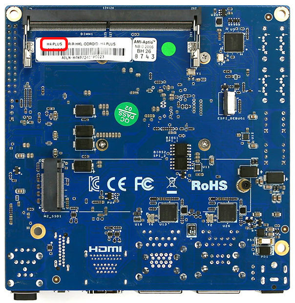
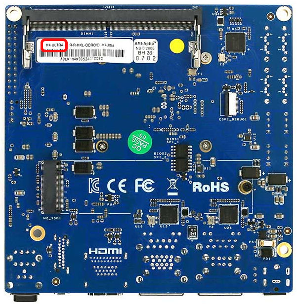
For the distinction between ODROID-H4, H4+, and H4-Ultra refer to the figure below
Have written H4, H4PLUS, and H4-ULTRA like in the red circle below pictures where on the bottom PCB inside SODIMM DDR5 Socket.
The terms HDMI, HDMI High-Definition Multimedia Interface, HDMI Trade dress and the HDMI Logos are trademarks or registered trademarks of HDMI Licensing Administrator, Inc.
HDMI, HDMI High-Definition Multimedia Interface(고화질 멀티미디어 인터페이스), HDMI 트레이드 드레스 및 HDMI 로고라는 용어는 HDMI Licensing Administrator, Inc.의 상표 또는 등록 상표입니다.
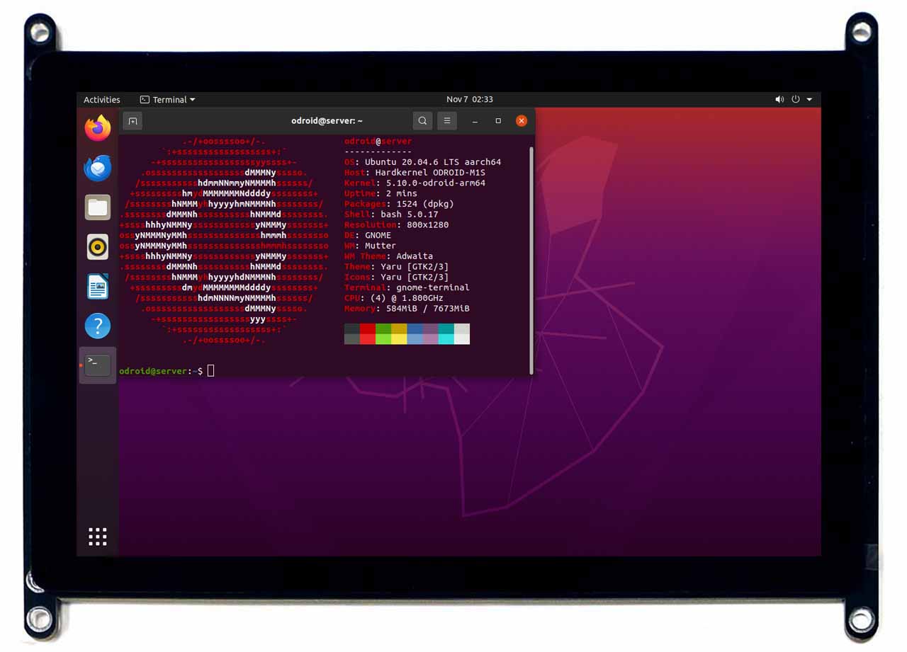
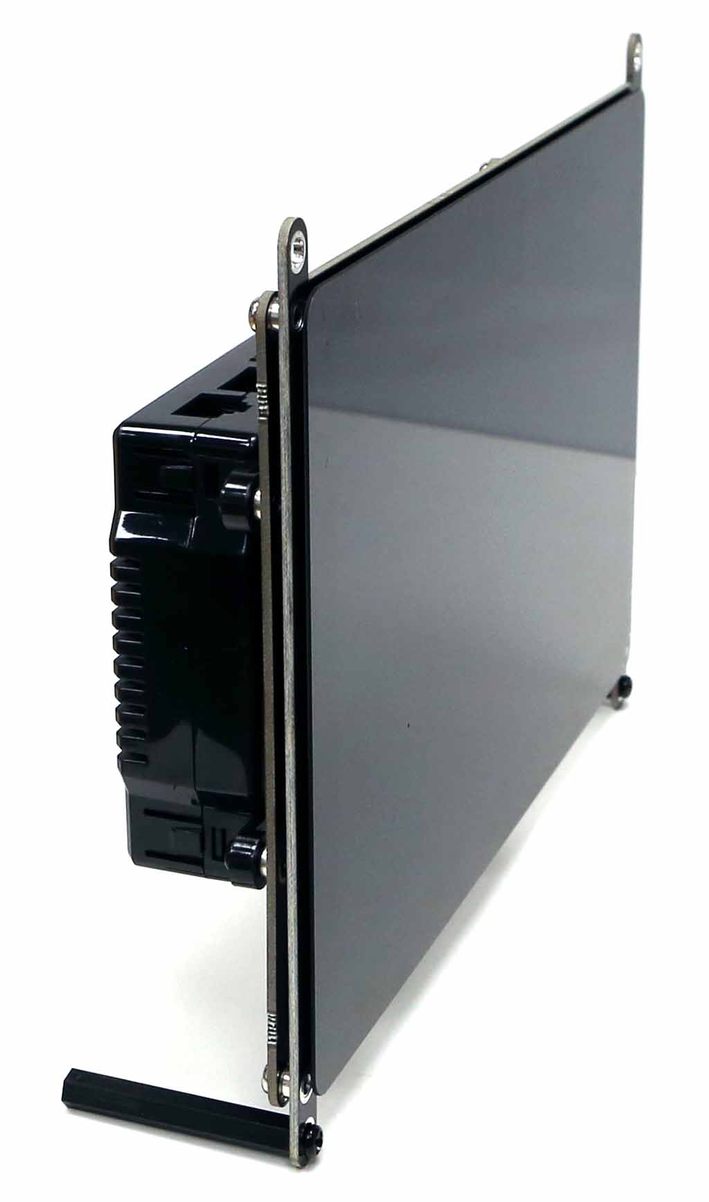
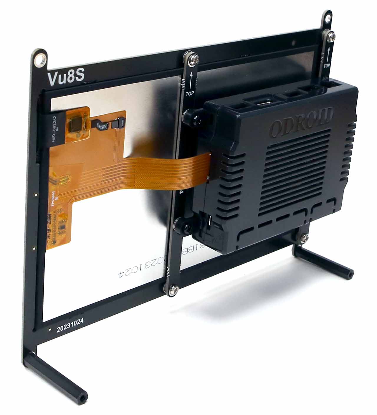
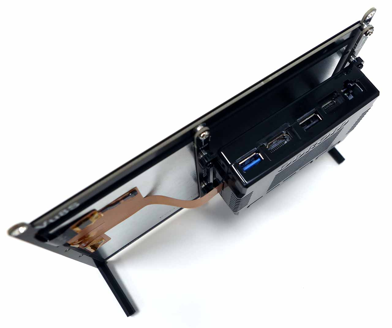
The four-lane MIPI-DSI port can be directly connected to a LCD panel. A 8inch 800×1280 wide viewing angle LCD and capacitive multi-touch screen is pre-assembled. The ODROID-Vu8S is dedicated to ODROID-M1S. It can only be used via a MIPI DSI Connector(J7) on M1S. The I type Bracket boards are required to dock Vu8S to assembled ODROID-M1S with case.
♦ If you activate the MIPI-DSI interface, the HDMI output function will be disabled automatically.
This is because HDMI and MIPI-DSI can NOT be used simultaneously due to system memory bandwidth limitations.
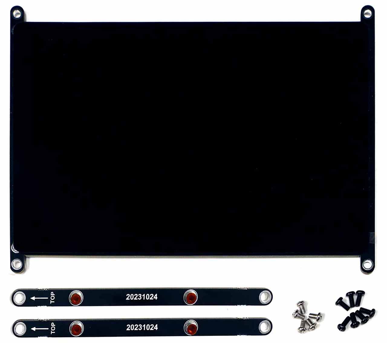
Package includes
A. Assembled 8inch TFT LCD + multi touch screen * 1EA B. M3 x 40(BLACK) Support * 3EA including a spare part C. M3 x 7(BLACK) Bolt * 7EA including a spare part D. M3 x 5(SILVER) Bolt* 5EA including a spare part E. Vu8S LCD Frame Board for M1S * 1EA F. Vu8S I form Bracket Board for M1S * 2EA
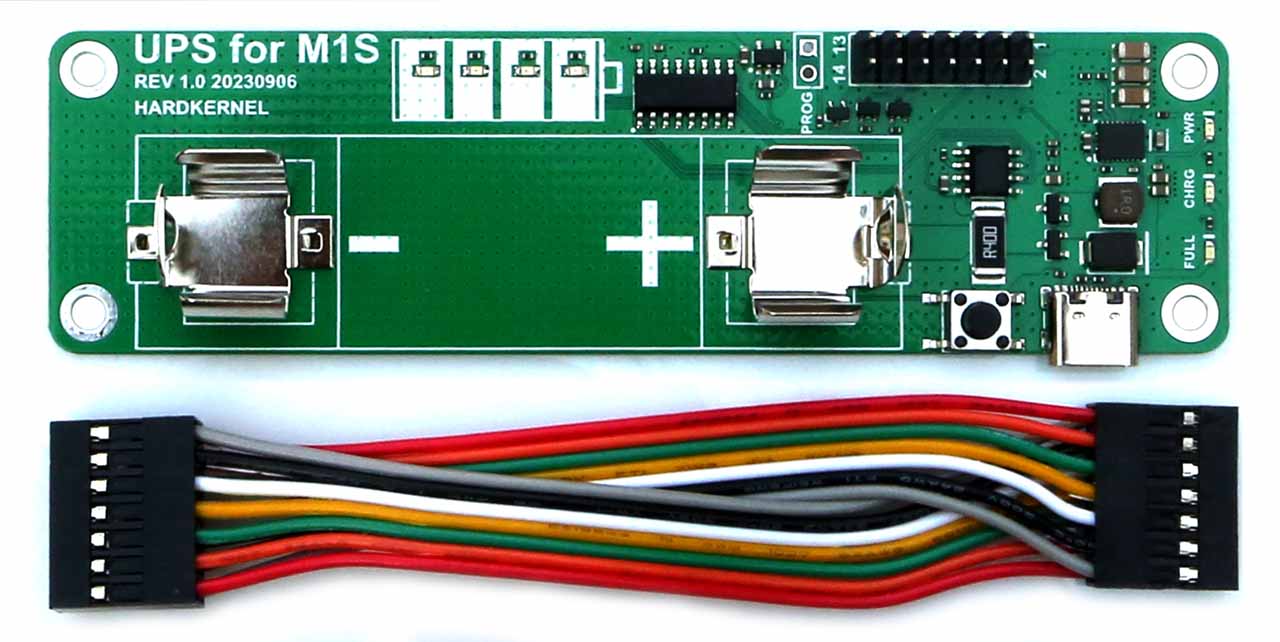
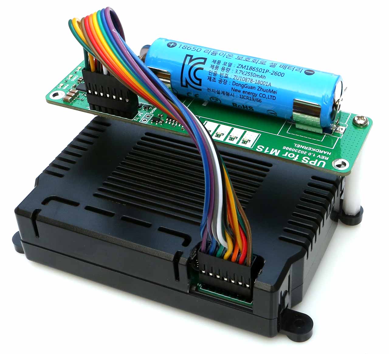
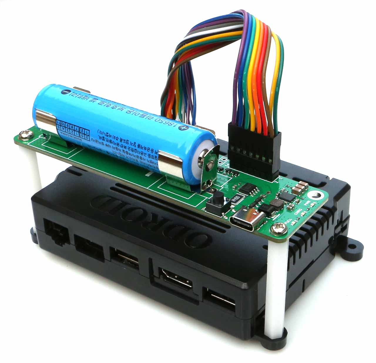
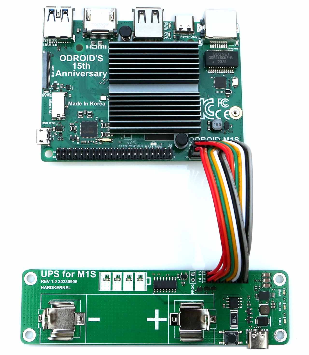
The UPS(Uninterrupted Power Supply) Kit is designed specifically for the ODROID-M1S.
It is equipped with a 18650 rechargeable Li-Ion battery holder, charger control IC and a 5Volt Boost DCDC. There is a small MCU on the board which measures the battery level and communicate with the ODROID-M1S board via USB interface. When the AC power source is removed, the UPS keeps supplying the power to the ODROID-M1S boards with the battery.
The M1S-UPS has a USB serial port(ttyACM) to communicate with so that it can trigger the shutdown process by sending a low battery warning. It will significantly reduce the risk of data loss by sudden power loss.When the AC power source becomes available again, the UPS will supply power to the ODROID-M1S again and trigger a power-on event automatically.
Specification
Power Input
Dc Input Voltage
DC 4.8V ~ 5.4V
DC Input Current
3A Min.
Charger
Charging Time
5 ~ 9 hours
Battery Charging Current
500mA Max.
Power Ouput
DC Output Current
3A Max.
DC Output Voltage
5.2 V
Recommended Battery
Type
Protected Li-Ion 18650 cylindrical cell
Capacity
2400~3600 mAh
Nominal Voltage
3.7 V
Estimated ODROID-M1S running time (500mA @ 5V)
About 3~4 hours with a fully charged battery
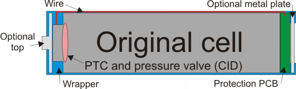
✔ The battery is not included in the package, so you have to buy a PROTECTED 18650 Li-Ion rechargeable battery in your local market and install it. The length of the 18650 Li-Ion battery with a built-in protection circuit is close to 68mm, which is about 3~4mm longer than the unprotected bare cell battery length of 65mm.
Since the retail market in many countries, including South Korea, does not allow the sale of unprotected lithium-ion rechargeable batteries, we designed it to use batteries that include a protection circuit.
For safety reasons, when purchasing batteries, please choose a reputable battery cell manufacturer if possible. As far as we know that Panasonic, LG, Samsung, and CATL are famous.
✔ Due to the Li-Ion chemical characteristics, the battery voltage level might go higher slightly when the load is very light.
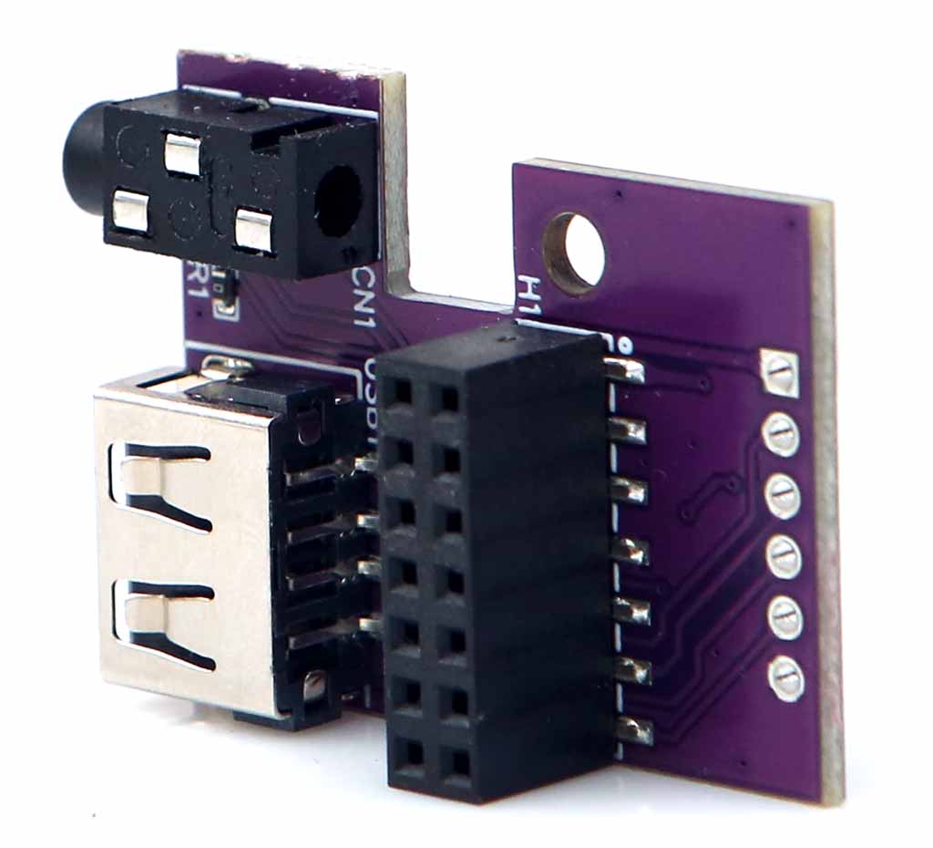
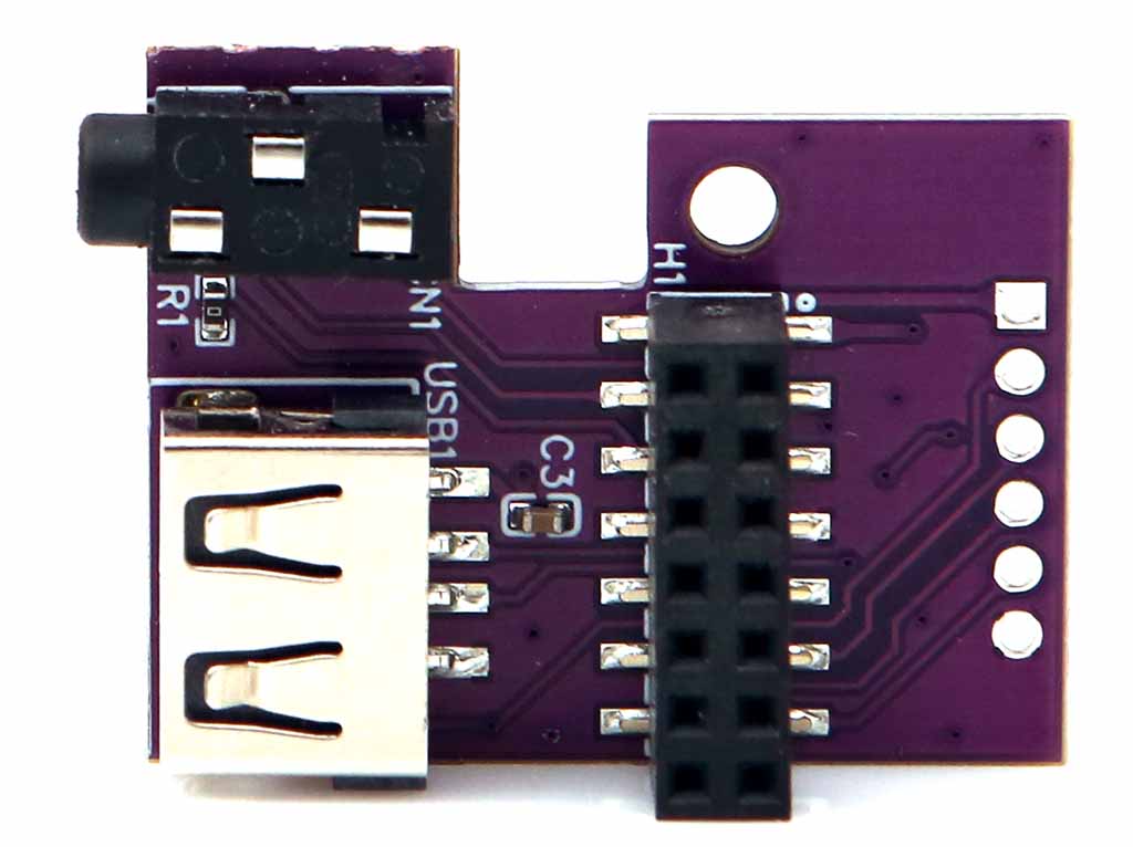
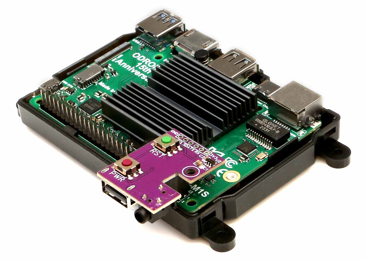
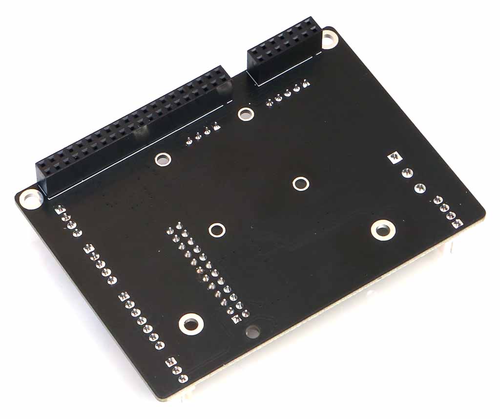
This is a convenient input/output port board that can be used by plugging directly into the 14-pin header connector of ODROID-M1S.
USB 2.0 host, Power button, Reset button, Audio line-out 3.5mm phone jack and I2C & UART buses are available on a small board.
System power noise may affect the audio circuitry, resulting in background noise in the audio output. Therefore, we recommend that our customers do not use the phone jack output in applications requiring high sound quality.
You have to remove the upper case to mount this IO board on the ODROID-M1S.
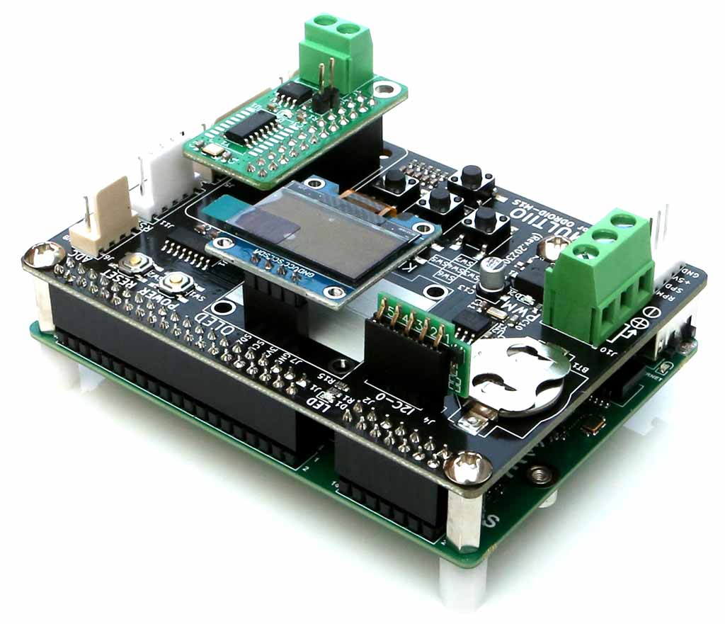
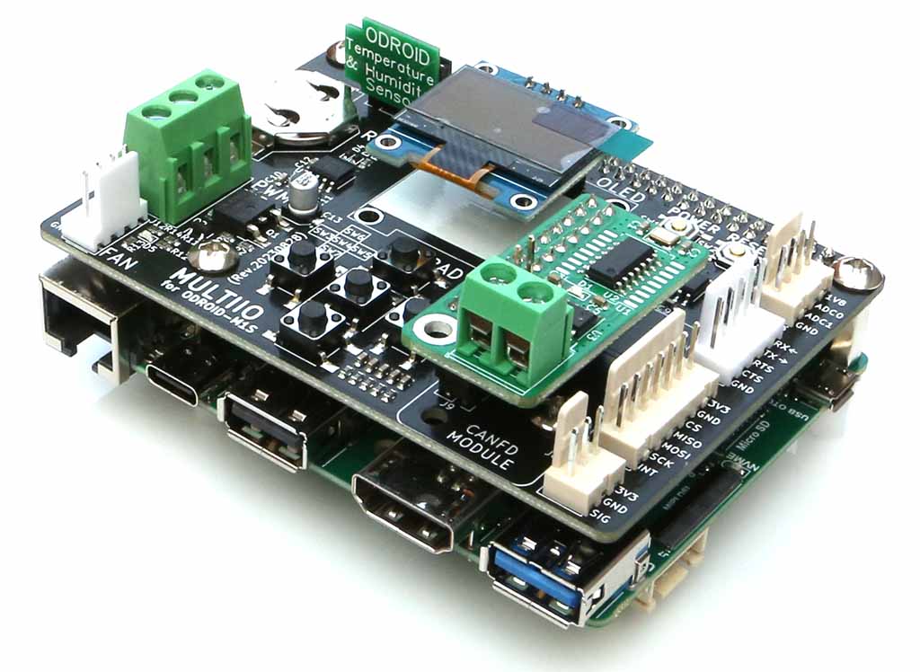
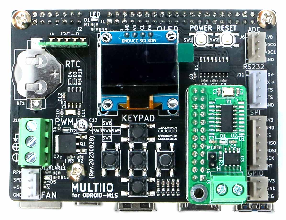
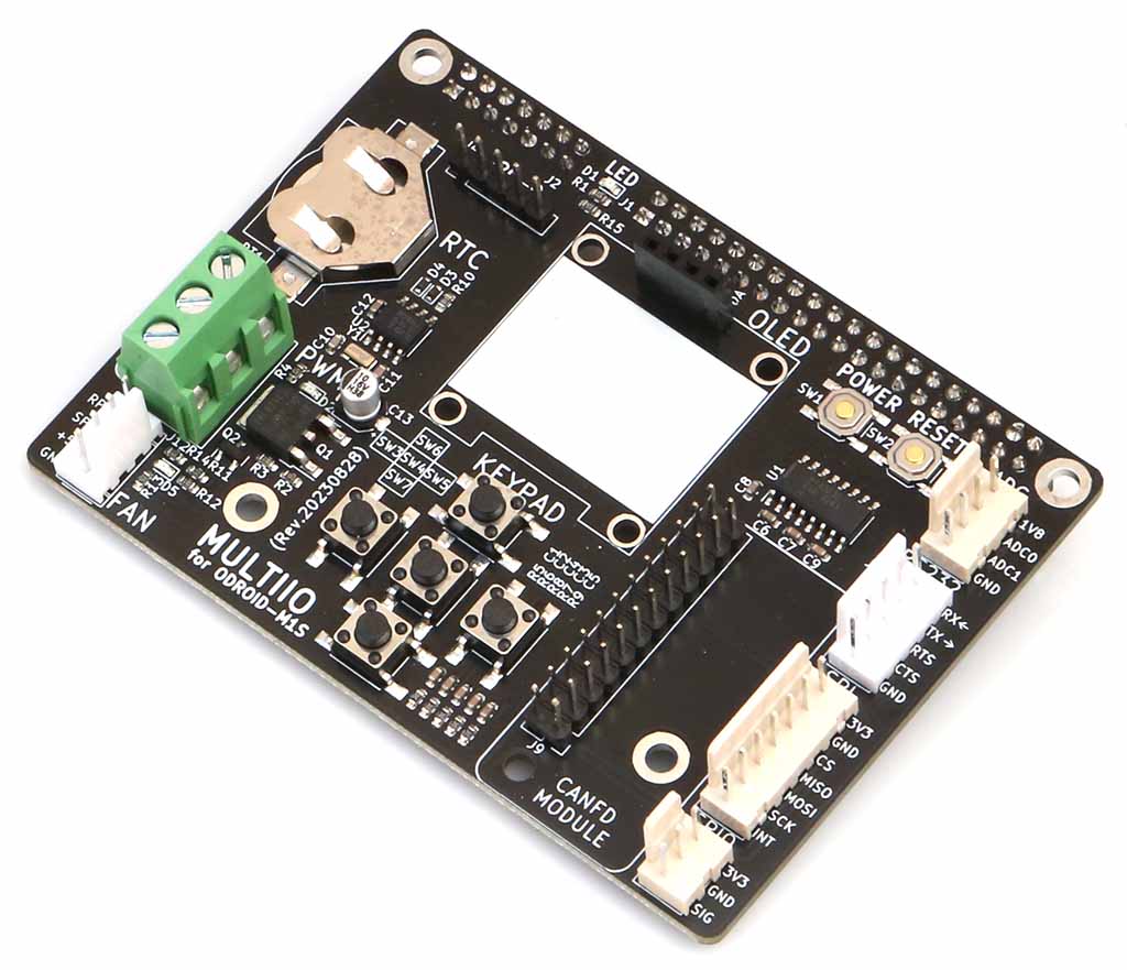
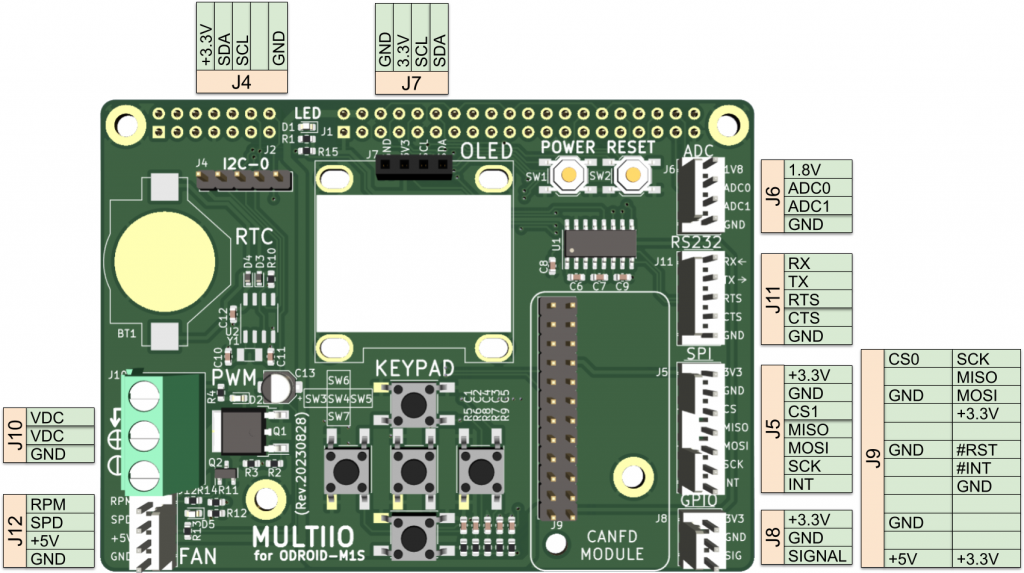
Multi I/O Training Board is designed to help one to add or extend various peripheral connections to GPIO pin header that used be done using jumper wires. Separating signals on GPIO header to multiple connections per different type of signals, this will help to easy wiring to peripheral devices and evaluate them. Also this board include several simple components that helps to test or use hardware functions.
! NOTE !
This product is only compatible with ODROID-M1S with 4/8GByte RAM + IO Header
Specifications
Form Factor
Board dimension : 90 (L) x 65 (W) x 16 (H) mm
I/O
2x I2C bus (J4 & J7, J7 is dedicated for 128×64 OLED display
1x LED
1x RTC (PCF8563) with backup battery socket (CR1620)
5x tack switches
2x buttons (SW1 is for power & SW2 is for board reset)
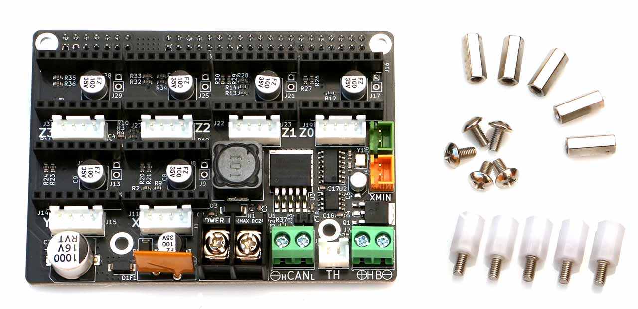
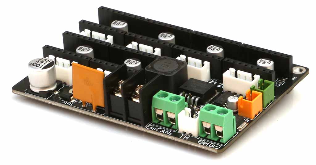
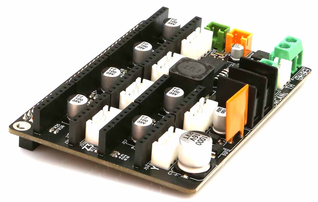
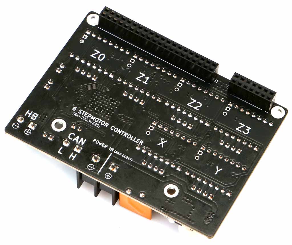
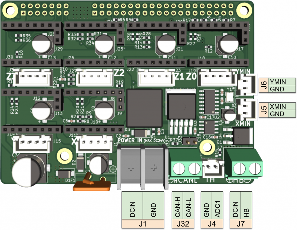
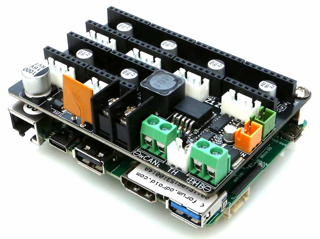
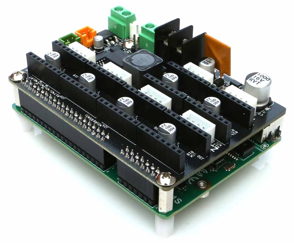
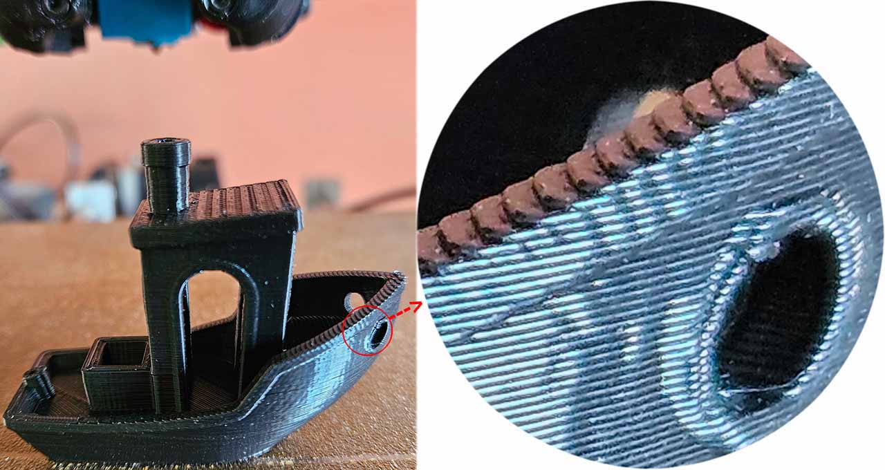
The Stepmotor Controller board is designed to control up to 6 step motors and support CAN-FD bus, its layout and pinout are especially organised for 3D printer.
On board DC step down power supply to provide 5V to ODROID-M1S
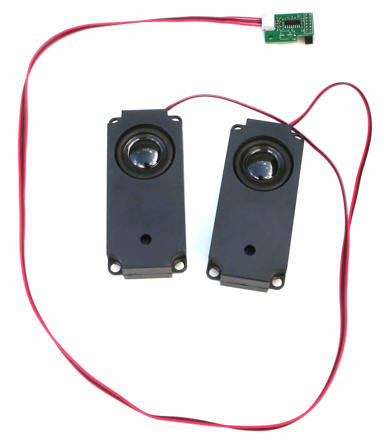
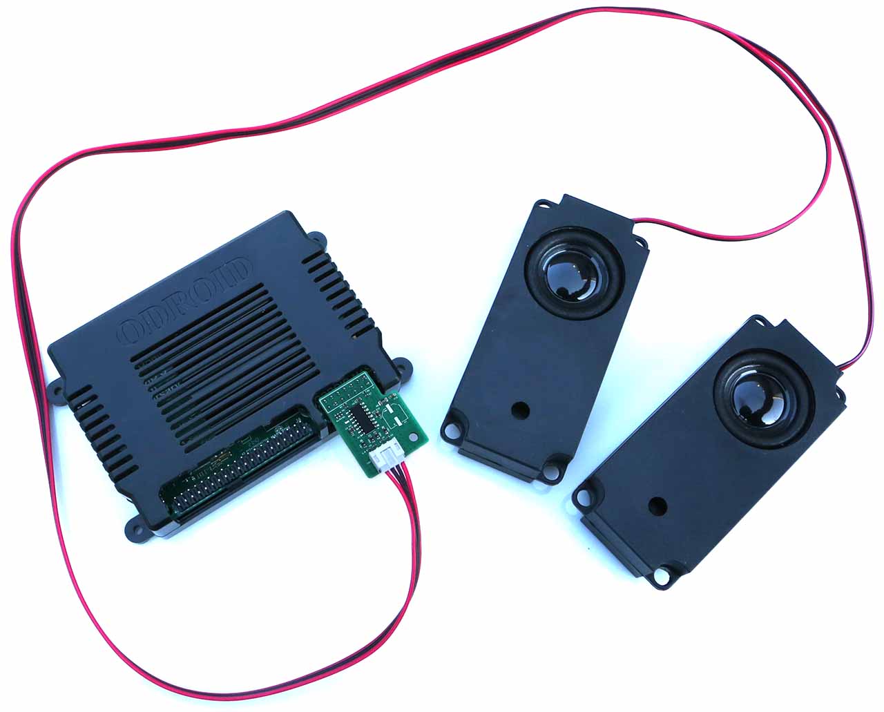
This is a speaker kit with on-board sound PAM8406 amplifier that can be used by plugging directly into the 14-pin header connector of ODROID-M1S.
♦ System power noise may affect the audio circuitry, resulting in background noise in the audio output. Therefore, we recommend that our customers do not use this board in applications requiring high sound quality.
♦ You have to cut out parts of the 14-pin on the upper case to mount this Speaker Kit on the ODROID-M1S.

 한국어
한국어